BIFS Tutorial
Complex 2D Geometry Nodes

|
|
BIFS TutorialComplex 2D Geometry Nodes |
|
The PointSet2D primitive is used to display a set of points in the 2D plane. The color used for the n-th point of the Coordinate2D.point field is the n-th color in the Color.color field. Therefore there must be the same number of coordinates than colors. If the Color.color field is not present or is empty the emissive color of the material of the shape is used.
Example :
<PointSet2D>
<color><Color color="1 1 1 0.5 1 1 1 0.5 1 1 1 0.5 0.5 0.5 0.5"/></color>
<point><Coordinate2D point="0 0 10 -10 20 +33 -30 -20 +50 -60"/></point>
</PointSet2D>
point.xmt, point.bt, point.mp4
These two primitives are very similar to the PointSet2D one. They have three more common fields: colorIndex, colorPerVertex and coordIndex. coordIndex is a list of indexes on the coordinates defined in the Coordinate2D.point field. colorIndex is a list of indexes on the colors defined in the Color.color field
IndexedLineSet2D is used to display one or several polylines. A polyline is a set of adjacent segments. The IndexedLineSet2D.coord field represents the list of points defining segments. The coordIndex field gives the ordered index of points defining the polylines. An index of '-1'indicates the end of the current polyline. If the coordIndex field is empty, all points in the Coordinate2D.point field define a single polyline.
The rules for polylines drawing are as follows:
The width and transparency of the line are defined as usual.
If the IndexedLineSet2D.color field is not empty, then :
If colorPerVertex is 'false' a single color is used for each polyline.
If colorIndex is not empty, colors are picked according to colorIndex. This field shall not have negative indexes and shall have as many indexes as there are polylines.If the Color node has N+1 colors, indexes range from 0 to N. The k-th index in colorIndex field gives the color of the k-th ployline.
If colorIndex is empty, colors are picked in the order they appear in Color.color. Hence there shall be as many colors as there are polylines. The k-th color of the Color node gives the color of the k-th polyline.
If colorPerVertex is 'true' each segment is drawn with a linear gradient between the segment end points colors. These are picked as follows:
If colorIndex is not empty, then each index in colorIndex matches an index in coordIndex or a point in Coordinate2D.
If colorIndex is empty then each color in Color.color matches an index in coordIndex or a point in Coordinate2D.point.
If IndexedLineSet2D.color is empty all polylines are drawn with the same color as for generic shapes. Note that IndexedLineSet2D is never filled.
The IndexedLineSet2D syntax is :
<IndexedLineSet2D colorPerVertex="true" colorIndex="0 1 2 3 4" coordIndex="0 1 2 3 4 -1">
<color><Color color="1 1 1 0.5 1 1 1 0.5 1 1 1 0.5 0.5 0.5 0.5"/></color>
<coord><Coordinate2D point="0 0 10 -10 20 +33 -30 -20 +45 -45"/></coord>
</IndexedLineSet2D>
The IndexedFaceSet2D primitive is used to display polygons. The IndexedFaceSet2D.coord field is the list of points to be used for the polygons. The IndexedFaceSet2D.coordIndex field gives the indexed list of points belonging to a single polygon. A value of '-1' indicates the end of a polygon. If the coordIndex field is empty all points in the Coordinate2D.point field are used to build a single polygon.
The coloring rules are the same as ones of the IndexedLineSet2D node. The IndexedFaceSet2D can be filled or not, depending on the material node of the shape.
The other fields are ignored in this tutorial.
The syntax is the same as the IndexedLineSet2D one.
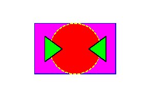
Exercice 5 : Use one of the preceding examples to draw the following scene:

The Curve2D node is used to draw cubic bezier curves and lines. The shape is filled, colored and stroke according to the material of the shape.
The syntax is :
<Curve2D type="2 3 0 1">
<point><Coordinate2D point="0 0 10 -10 20 +33 -30 -20 +45 -45 0 0 -30 -30 -30 20"/></point>
</Curve2D>
The Curve2D.point field holds the list of points to be used. The Curve2D.type field gives the type of curve to use with the points. Each type describes a curve constyruction command. Each command starts at the current point and uses a variable number of points. Once the command is applied, the final point becomes the current point. Type 0 indicates a move command, that is "move the current point to the given point". The first moveTo is always implicit and uses the first point of the Coordinate2D. Type 1 indicates a line command, that is "draw a line to the given point". Type 2 indicates cubic bezier curve and uses 3 points. The first 2 points are the control points of the curve and the last one is the final point of the curve. Type 3 indicates a cubic bezier curve after a line or another curve and uses 2 points. The start point is the current point, the second control point is the first point used, the first control point is the symetric of the second control point with respect to the starting point. The arrival point is the second point used.
Here is the traduction of the above example:
"Start curve at (0,0). Draw a cubic bezier curve to (-30,-20) with control points (10,-10) and (20,33). Draw a cubic bezier curve to (0,0) with control points (-80,-73) and (+45,-45). Move to (-30,-30). Draw a line to (-30,20)."